Wij zijn |
TPM-sniffing with Saleae logic analyzer [2025]
Imagine the following scenario: a malicious attacker is trying to steal your data. You are aware of the risk and have secured your PC with a strong password. The attacker knows that brute-forcing this password would take too long — or worse, might trigger a lockout. So instead, the attacker steals the laptop and takes it home. Once there, they open the laptop, physically remove the hard drive, and connect it to their own computer. Within seconds, they’ve bypassed your “very secure” password and gained full access to your data.
To prevent attacks like this, the Trusted Platform Module (TPM) was introduced. A TPM chip encrypts the hard drive using strong cryptographic techniques, making the data unreadable without proper authorization. TPM is most associated with BitLocker (Windows), but it’s also used with tools like FileVault (macOS) and dm-crypt/eCryptfs (Linux and ChromeOS). Disk encryption with a TPM chip is considered a secure and highly recommended solution. However, it introduces a trade-off: users need to enter a password every time they boot. To solve this inconvenience, encryption software often offers an option to automatically unlock the drive using the TPM.
Convenient? Absolutely. Secure? Well…
This automatic unlocking opens the door to a lesser known but very real threat: hardware sniffing. In this blog, we’ll dive into how such an attack works, what’s required to perform it, and share our hands-on experience with sniffing communication from a TPM chip.
TPM‑sniffing with Saleae logic analyzer [2025]
How the TPM key works
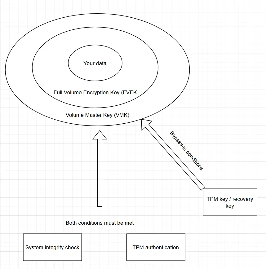
When using BitLocker with TPM support, a layered key structure is used to protect encrypted data. Here’s how the decryption process typically works:
- Startup Key (TPM-sealed key)
Stored securely within the TPM. This key is only released when specific platform integrity checks (such as BIOS/UEFI, bootloader, and OS measurements) pass. It acts as a gatekeeper. This is your Key, the one you save In a notepad or file. - Volume Master Key (VMK)
The Startup Key is used to decrypt the VMK, which is the core key used to control access to the volume’s encryption. This is the key that can be sniffed with a logic analyser. - Full Volume Encryption Key (FVEK)
- The VMK decrypts the FVEK, the actual key used to encrypt and decrypt the contents of the disk.
How the TPM chip communicates
A TPM communicates with the CPU through the Platform Controller Hub (PCH), this is a central chip on the motherboard which used to be called the Southbridge. The PCH is responsible for communication with most of the hardware, such as the display, hard drive and usb drives.
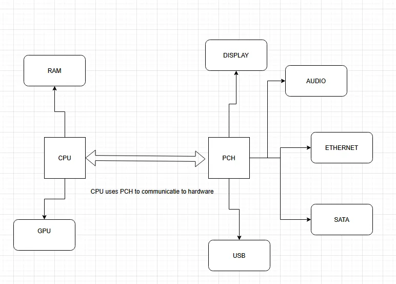
The PCH is often found nearby the CPU, as they communicate a lot to control the hardware. In some cases, they can be found under the same thermal shield. The PCH chip is much smaller than the CPU chip.
Protocols
The TPM chip can communicate with the PCH over three protocols:
Protocol
Used In
Speed
Direction
LPC (Low Pin Count)
TPM 1.2 (older systems)
Slow
Multiplexed
SPI (Serial Peripheral Interface)
TPM 2.0 (modern systems)
Fast
Full-duplex
I²C (Inter-Integrated Circuit)
Embedded TPMs (IoT devices)
Slow
Half-duplex
In this blog we will focus on the SPI protocol, this is the communication protocol that is most common in computers and laptops. LPC is mostly used on older devices and I2C finds its function in embedded devices such as IoT devices.
The SPI (Serial Peripheral Interface) is a synchronous serial communication protocol. It uses a master/slave model where the master (usually the PCH) initiates all communication. It uses four logic lines:
| Signal | Name | Description |
|---|---|---|
| SS (or CS) | Slave Select (or chip select) | Tells the TPM it's being addressed. |
| SCLK | Serial Clock | Clock signal from the master. |
| MOSI | Master Out, Slave In | Data sent from the PCH to the TPM. |
| MISO | Master In, Slave Out | Data sent from the TPM back to the PCH. |
Example of a typical read transaction:
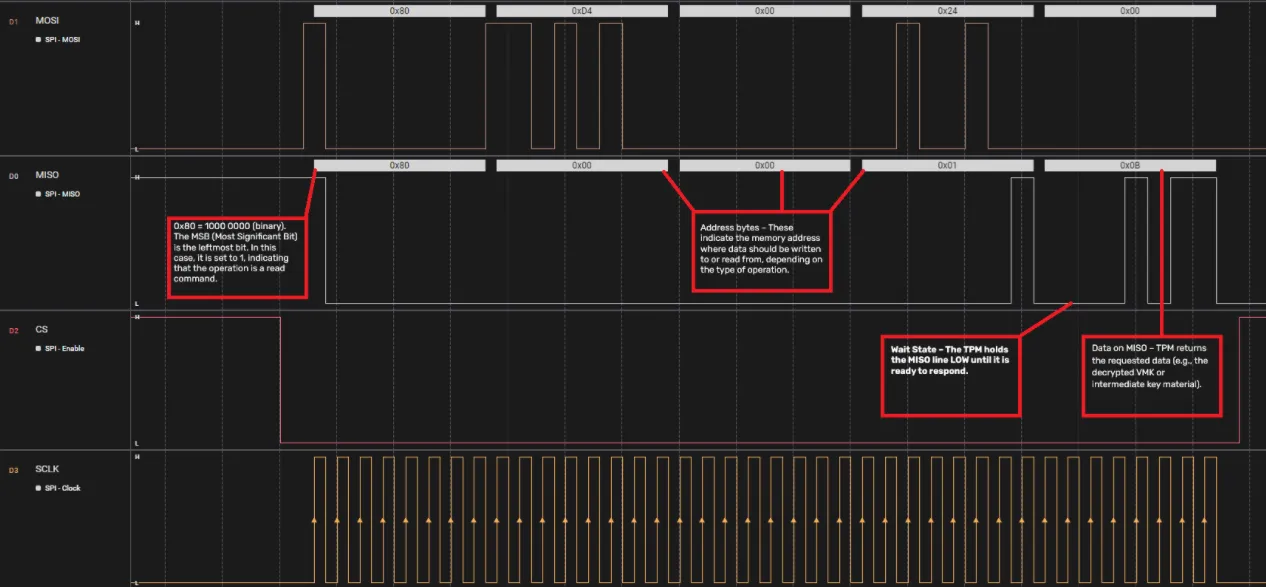
This waveform shows how a typical read transaction works:
- SS (CS) goes LOW – the PCH starts a transaction with the TPM.
- Command Byte on MOSI – tells the TPM whether it’s a read or write, and how much data is requested.
- If the MSB is 1, it’s a read command.
- The lower 6 bits specify how many bytes to transfer.
- Address Bytes on MOSI – tells the TPM which memory address to read/write.
Our experience
To successfully extract encryption keys from a TPM chip, thorough preparatory research is essential. This process involves both physical disassembly and technical investigation of the target system.
In our case, the target was an HP ProBook 650 G8 Notebook PC IDS Base Model. The preparation phase focused on disabling anti-tampering protections and safely disassembling the laptop to gain access to the TPM chip. Several security features—such as Secure Boot and integrity checks—were disabled via the BIOS.
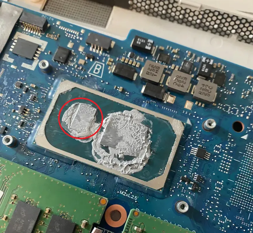
The disassembly was carried out using a hardware toolkit and a detailed video guide. After removing the motherboard, the TPM chip was identified based on a GitHub page and PCB schematics. Visual inspection confirmed the presence of an Infineon SLB9670VQ TPM chip on the underside of the motherboard.
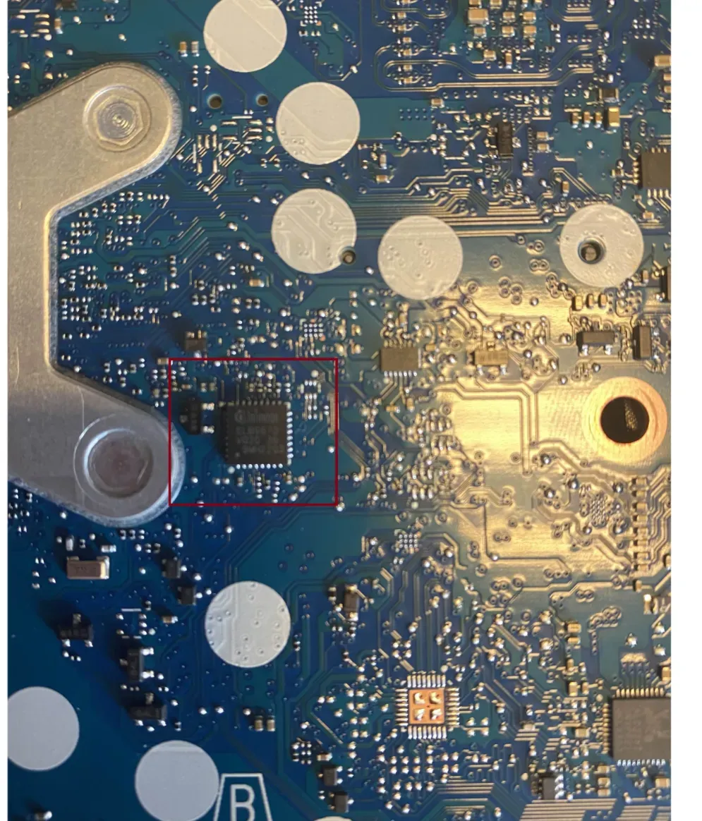
The next step was to locate the four logic lines required for sniffing: MISO, MOSI, CS, and SCLK. These lines must be tapped with a logic analyzer to intercept the Volume Master Key (VMK). There are two main ways to locate these lines:
- Signal pattern analysis during runtime
- Using the TPM chip’s datasheet
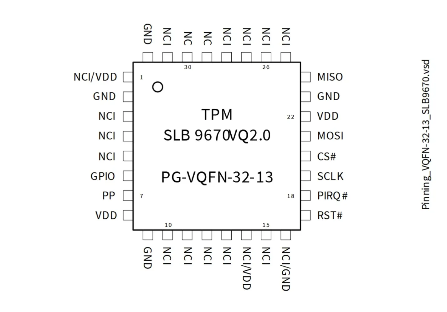
Fortunately, the SLB9670VQ datasheet was available online and showed the exact pinout for these logic lines.
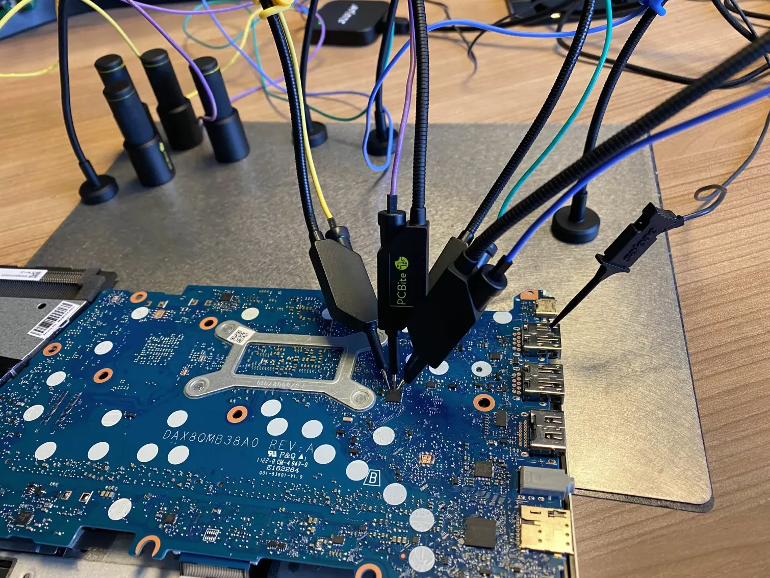
Using a logic analyser
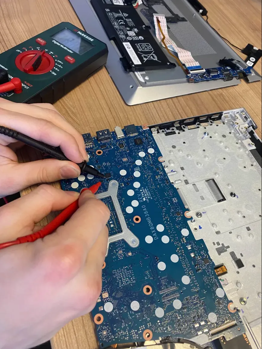
The logic analyzer setup included a Saleae Logic 8 combined with a PCBite probe kit. The standard clip probes that come with the Saleae Logic were too large for the TPM pins, which are embedded into the motherboard and not accessible with latching hooks.
We attempted to find larger pins on the motherboard to latch onto, by using a multimeter in continuity mode. A couple of larger pins were found, however the clip probes stil had trouble latching on. To solve this a PCBite probe kit was purchased.
Example of pin size compared to the hooks of the Saleae logic analyzer.
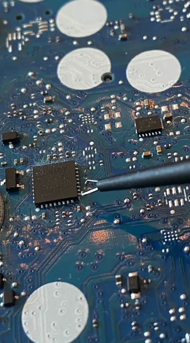
However, the SQ10 probes from the PCBite kit were small and precise enough to rest directly on the exposed pads.
The TPM’s communication was captured using Saleae Logic software, alongside two custom protocol extensions for TPM SPI analysis. However, the sampling rate of the Saleae Logic 8 proved insufficient to fully capture the high-speed SPI traffic between the TPM and the platform controller hub (PCH).
The standard Saleae Logic 8 provides a maximum sampling rate of 100 MS/s (mega samples per second) when using up to two channels. Since our TPM sniffing required four channels (MISO, MOSI, SCLK, and CS), the software automatically reduced the sampling rate to 50 MS/s.
To reliably decode SPI communication, the analyzer should sample at least 4–5 times faster than the SPI clock speed, as per standard digital signal analysis guidelines In our case, the SPI bus operated at around 66 MHz, which exceeds the logic analyzer’s effective sampling rate. This mismatch meant the analyzer was only capturing ~¾ of the necessary data points per clock cycle, leading to incomplete or corrupted signal data.
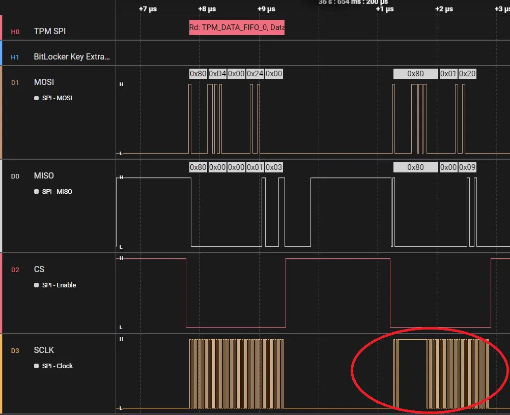
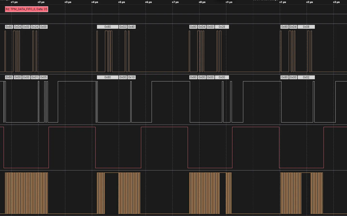
You can clearly spot missing chunks by examining the SCLK line, which should be continuous during data transmission. The analyzer missed multiple cycles, leading to incorrectly interpreted data. Despite this, portions of the capture were valid and usable, especially the start of the VMK structure.
The VMK key has a recognizable header format. This was confirmed by reviewing the source code of the TPM sniffing extension used. The extension has also been used in several other successful TPM sniffing case studies. The VMK header has the following template according to the following website:
2c000[0-6]000[1-9]000[0-1]000[0-5]200000Out of 12 captures, one contained an incomplete but recognizable header:
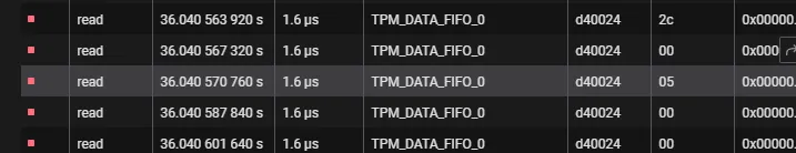
These 5 inputs from the data table don’t follow the template exactly, however upon deeper inspection of the data we can find incomplete data.
Now if we mark all the missing data as XX and write down the data we do have, we come back with the following data:
2c 00 05 xx xx xx xx 00 xx xx xx 00Holding this next to the template we can see the similarities between our found (incomplete) data and the header key:
2c000[0-6]000[1-9]000[0-1]000[0-5]200000The next step is to extract the following 32 bytes of data. Just like before, any unreadable or incomplete sections are marked as “XX”, while the valid bytes are written down. This gives us a partially complete VMK candidate.
XX BF 4C XX XX XX 53 XX A3 XX XX XX XX 09 XX XX XX XX XX 50 XX 57 XX 9A 89 A5 FE XX XX XX XX XX 00 XXBy comparing this candidate with data from other captures, we can start matching known patterns and filling in the gaps. At this stage, reconstructing the VMK becomes a jigsaw puzzle: we identify consistent byte sequences across captures, align them with the expected VMK structure, and iteratively rebuild the full 32-byte key. This comparative analysis led to the following reconstruction:
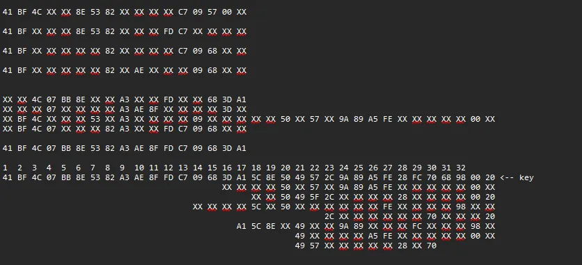
Each partial segment was a piece of the final picture, and through iteration, byte-matching, and cross-referencing known patterns in BitLocker’s cryptographic structure, we could infer the complete key.
41 BF 4C 07 BB 8E 53 82 A3 AE 8F FD C7 09 68 3D A1 5C 8E 50 49 57 2C 9A 89 A5 FE 28 FC 70 68 98Decrypting the BitLocker-Protected Drive
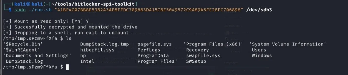
With the reconstructed VMK in hand, we were ready to test whether it would allow access to the encrypted BitLocker volume. The next phase of the attack involved physically removing the internal hard drive from the target system and connecting it to an analysis workstation.
To decrypt the drive dislocker is used, this an open-source utility specifically designed to mount and decrypt BitLocker-encrypted drives on Linux-based systems. Dislocker takes the extracted VMK and attempts to unlock the encrypted volume by providing it as a key input instead of relying on the system’s TPM. Once connected, we used this script (which implements dislocker) to decrypt the drive!
Conclusie
Hoe kunnen wij u helpen?


Offensive Entra ID (Azure AD) and Hybrid AD security – Outsider Security review
In this blog post, I share my personal journey and insights from undertaking the Certified Azure Red Team Expert (CARTE) certification offered by Altered Security.
The WiFi Pineapple: Basic Usage
The Wi-Fi Pineapple, developed by Hak5, is a powerful tool designed for wireless network auditing. Its versatility makes it ideal for red teamers and physical pentesters who need to assess wireless environments quickly and efficiently. In this blog post, we’ll go through the basic usage of the Wi-Fi Pineapple, explain how it works, and demonstrate its potential in a controlled test scenario.
KeyCroc (Hak5) tutorial: wat is het en hoe werkt het?
De KeyCroc van Hak5 is een fysieke aanvalstool die toetsaanslagen onderschept en zelfstandig commando’s kan uitvoeren via HID-simulatie, ook wel fysieke keylogger genoemd. In deze blog wordt toegelicht hoe de KeyCroc werkt en hoe hij geconfigureerd wordt.